
Views: 0 Author: Site Editor Publish Time: 2026-08-23 Origin: Site


High-frequency base station networks, including modern 4G LTE and 5G deployments, operate with minimal margin for signal degradation. This incredibly tight tolerance makes the selection of individual jumper cable components critical to overall system integrity. Jumpers serve as the vital bridges connecting main feeder lines to antennas or remote radio heads (RRHs). Within these components, the internal conductor acts as the primary variable dictating essential metrics like insertion loss, Passive Intermodulation (PIM), and mechanical durability.
Engineers must carefully weigh these variables during network design to ensure optimal transmission quality. Different metals and geometries perform radically differently under physical stress and electromagnetic demands. Evaluating the precise RF jumper cable conductor material and structural design is necessary to balance electrical efficiency with the mechanical realities of tower installation. You will learn how material choices impact attenuation rates and why specific wire designs continue to dominate modern cell site constructions.
Conductor material and geometry strictly define a jumper cable’s attenuation rate and flexibility.
High-frequency applications rely heavily on the "skin effect," making surface plating more critical than core material volume.
Solid conductors offer the lowest loss but introduce installation risks; stranded conductors provide necessary flexibility for tight routing.
Silver Plated Copper Stranded Wire represents the optimum balance for high-frequency, low-loss, and mechanically demanding base station environments.
Signal attenuation caused by poorly chosen jumper materials rapidly cascades into larger network performance issues. When you install a Base Station RF Cable lacking high-grade internal metals, signal loss naturally increases across the transmission path. This forces the baseband unit to push more power simply to achieve baseline coverage. Over time, this inefficiency shrinks the effective coverage footprint and degrades user experience at the cell edge. Network planners must establish clear success criteria to avoid this operational trap.
To maintain peak performance, engineers evaluate jumper cables against three strict criteria:
Insertion Loss Tolerance: Networks enforce strict limits per meter based on operating frequency. Sub-6 GHz installations forgive more loss than mmWave deployments. You must align material properties to the specific frequency band to keep signal drops within acceptable thresholds.
PIM Mitigation: Material purity prevents frequency interference. Poor structural integrity introduces microscopic arcs between metal surfaces. These small arcs generate PIM, which heavily degrades the critical uplink signal. We look for pristine surface conditions and stable geometries to prevent this.
Mechanical Reliability: Towers constantly sway in the wind. This movement causes persistent vibration. Jumpers also route through extremely tight spaces between the RRH and the antenna array. You need a design offering strong resistance to metal fatigue and repetitive physical stress.
The core metal directly dictates how a signal travels and how the cable physically behaves on the tower. Industry standards highlight three primary choices, each carrying distinct advantages and notable implementation risks.
Manufacturers create CCA by bonding a thin layer of copper over an aluminum core. It provides a lightweight profile and lowers material expenses. However, the risks often outweigh these benefits in mission-critical applications. CCA exhibits higher baseline electrical resistance. If moisture breaches the outer jacket, the exposed aluminum corrodes rapidly through galvanic action. Furthermore, dynamic tower loads expose thermal expansion mismatches between the aluminum core and the copper skin, leading to long-term structural failure.
Bare copper remains a historical industry standard for many low-frequency applications. It delivers excellent overall conductivity and provides highly predictable thermal behavior under varying weather conditions. Despite these pros, it weighs significantly more than aluminum alternatives. More importantly, bare copper remains highly subject to oxidation over time. Copper oxide acts as a semiconductor, which aggressively degrades high-frequency signal flow and creates massive PIM spikes over the installation lifecycle.
This premium material maximizes the physical "skin effect." At high frequencies, electromagnetic signals travel almost exclusively on the outermost layer of the conductor. Silver drastically reduces insertion loss compared to bare copper due to its superior surface conductivity. While it commands a higher initial price point, the enhanced signal preservation makes it highly justifiable for high-density, high-frequency base station arrays.
Material Type | Conductivity Profile | Weight Factor | Oxidation Resistance | Best Application Scenario |
|---|---|---|---|---|
Copper-Clad Aluminum (CCA) | Moderate (skin effect dependent) | Very Light | Poor (High risk of galvanic corrosion) | Low-budget, temporary indoor builds |
Bare Copper (BC) | Excellent | Heavy | Low (Forms semiconductive oxides) | Sub-3GHz legacy macro sites |
Silver-Plated Copper (SPC) | Superior (Optimized for skin effect) | Heavy | Excellent (Silver oxide remains conductive) | 5G mmWave and high-density RRH arrays |
Common Mistake: Field technicians sometimes assume thicker bare copper cores automatically improve high-frequency transmission. They fail to account for the skin effect. Upgrading to a thicker wire adds unnecessary weight and rigidity without improving the actual surface path where the 5G signal travels.
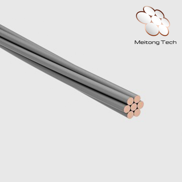
Once you select the core material, the physical geometry becomes the next critical decision point. Engineers must choose between solid and stranded configurations. This choice strictly dictates how easily installers can route the cables without causing invisible internal damage.
Solid conductors feature a single, unbroken cylindrical metal core. They are best utilized in fixed, straight runs requiring minimal movement over time. Because the surface is perfectly continuous, they yield the absolute lowest theoretical attenuation. PIM stability remains superior because there are no moving internal parts to create microscopic friction.
However, solid conductors carry a severe implementation risk. Cramped RRH enclosures force technicians to make incredibly tight bends. Solid wires lack physical flexibility and kink easily under pressure. These bends often cause micro-fractures in the copper during installation. These hidden fractures ruin signal performance and demand immediate replacement upon testing.
Stranded conductors consist of multiple smaller wires twisted together to form a single larger conductor. Manufacturers design them specifically for complex routing. They provide the necessary high flexibility jumper applications demand on a congested cell tower. The trade-off involves a slight increase in theoretical attenuation due to the uneven surface profile.
The main implementation risk stems from multi-wire friction. Microscopic movements between strands can technically impact PIM if the cable experiences violent vibration. Furthermore, poorly terminated ends will cause PIM spikes. This reality requires precision connectorization. Technicians must solder or crimp the connectors perfectly to fuse the strands into a single electrical point.
Best Practice: Always check the manufacturer's stated minimum bend radius. Forcing a solid cable past this limit guarantees internal damage. If your tower design requires routing paths tighter than the specified radius, you must switch to a stranded design to maintain physical integrity.
Modern telecommunications networks demand solutions bridging the gap between electrical perfection and physical reality. We find a vital technical intersection here. By combining the mechanical flexibility of stranded geometry with the ultra-low resistivity of a silver surface, engineers solve multiple field challenges simultaneously. Silver Plated Copper Stranded Wire consistently provides the definitive standard for low-loss jumpers.
At advanced 5G frequencies, the signal penetration depth into the metal becomes practically microscopic. Signals travel exclusively on the very outer edge of the strands. Silver delivers vastly superior conductivity on these surface areas. This specialized plating efficiently mitigates the natural attenuation penalty traditionally associated with stranded designs. You get the flexibility of multiple strands without sacrificing the high-frequency transmission capability.
Longevity and environmental stability also improve dramatically. Bare copper oxidizes rapidly when exposed to humidity or temperature swings. Copper oxide severely blocks RF signals. Conversely, silver plating actively protects the underlying copper core. Even if silver oxidizes, silver oxide remains highly conductive. This unique chemical property stabilizes insertion loss metrics over a typical 10 to 15-year base station lifecycle. You secure reliable performance across harsh seasonal changes and eliminate erratic signal drops.
Selecting the right components requires a systematic approach. Rather than relying on generic spec sheets, utilize this structured framework to align your material choices directly with your specific cell site demands.
Map the Frequency Requirements: Begin by identifying the highest operating frequency of the intended antenna sector. For legacy 3G or low-band 4G, standard materials might suffice. However, for any frequencies above 3GHz, you should mandate silver-plated options. This proactive step effectively controls skin-effect losses and ensures maximum signal reach from the remote radio head.
Define Environmental & Routing Strain: Evaluate the physical space available on the tower mounting brackets. Measure the required bend radius for the jumper paths. If the routing requires dynamic bending around structural steel, or if the region experiences high wind loads requiring intense vibration endurance, completely disqualify solid conductors. Opting for stranded designs prevents inevitable fatigue failures.
Analyze the PIM vs. Flexibility Trade-off: We acknowledge stranded conductors historically risk higher PIM generation due to internal friction. You must mitigate this risk through rigorous vendor vetting. Verify the stranded conductor cables hold a sweeping PIM certification from the manufacturer. Look specifically for guaranteed ratings of ≤ -160 dBc or better under flexure conditions. This proves the manufacturer uses tight stranding tolerances and proper connectorization techniques.
The right jumper component is never a generalized choice. The specific operating frequency, tower flexibility needs, and stringent PIM requirements of the individual cell site strictly dictate the ideal material. Ignoring these variables leads to degraded network coverage and fragile tower infrastructure.
For low-loss, high-reliability base station applications, silver-plated copper stranded conductors eliminate the traditional compromise between signal integrity and installation flexibility. They provide the necessary surface conductivity for advanced 5G signals while easily handling the tight routing paths required behind modern antenna arrays.
Take proactive next steps to safeguard your network builds. Consult with your cable manufacturing partner directly. Ask them for detailed frequency attenuation charts covering the exact lengths you plan to deploy. Furthermore, request comprehensive environmental testing data, focusing specifically on PIM stability under active flexure, prior to committing to bulk procurement.
A: As operating frequencies rise, electromagnetic signals migrate to the outermost layer of the metal. This phenomenon means surface conductivity becomes far more critical than core thickness. Adding a highly conductive surface, like silver plating, ensures signals travel with minimal electrical resistance. This drastically lowers attenuation rates without requiring thicker, heavier wire cores.
A: Solid copper provides exceptional loss metrics and stable PIM performance. However, it lacks vital physical flexibility. Base station setups require routing through extremely tight bending radii between main feeders, remote radio heads, and antennas. Forcing a solid wire through these cramped spaces causes kinking and micro-fractures, which permanently damages the transmission path.
A: Historically, stranded wires worsened PIM due to microscopic friction between individual strands during physical movement. Today, modern manufacturing processes effectively mitigate this issue. By enforcing tight stranding tolerances and applying high-quality silver plating, manufacturers stabilize the electrical path. These improvements allow stranded designs to comfortably meet strict carrier-grade PIM standards.
A: You can expect a reliable operational lifecycle of 10 to 15 years in typical outdoor tower deployments. This longevity relies heavily on applying proper weatherproofing tape at the connector junctions. Keeping moisture out prevents internal corrosion. The silver layer naturally protects the underlying copper, ensuring insertion loss remains stable despite years of fluctuating temperatures.


